12 Wire Motor Wiring Diagram Without Start
This applies to all old cub cadet, ford, jacobsen, john deere, wheel horse, case, and simplicity garden tractors.  Ok if we assume the motor is delta wound, and was set up 440v, just start walking through the connections that are known.
6 Lead Wye Start Delta Run Wiring Diagram 480 Motor Wiring Diagram 12 Wire Full Version Hd
With this kind of an illustrative guidebook, you are going to have the ability to troubleshoot, avoid, and full your tasks easily.
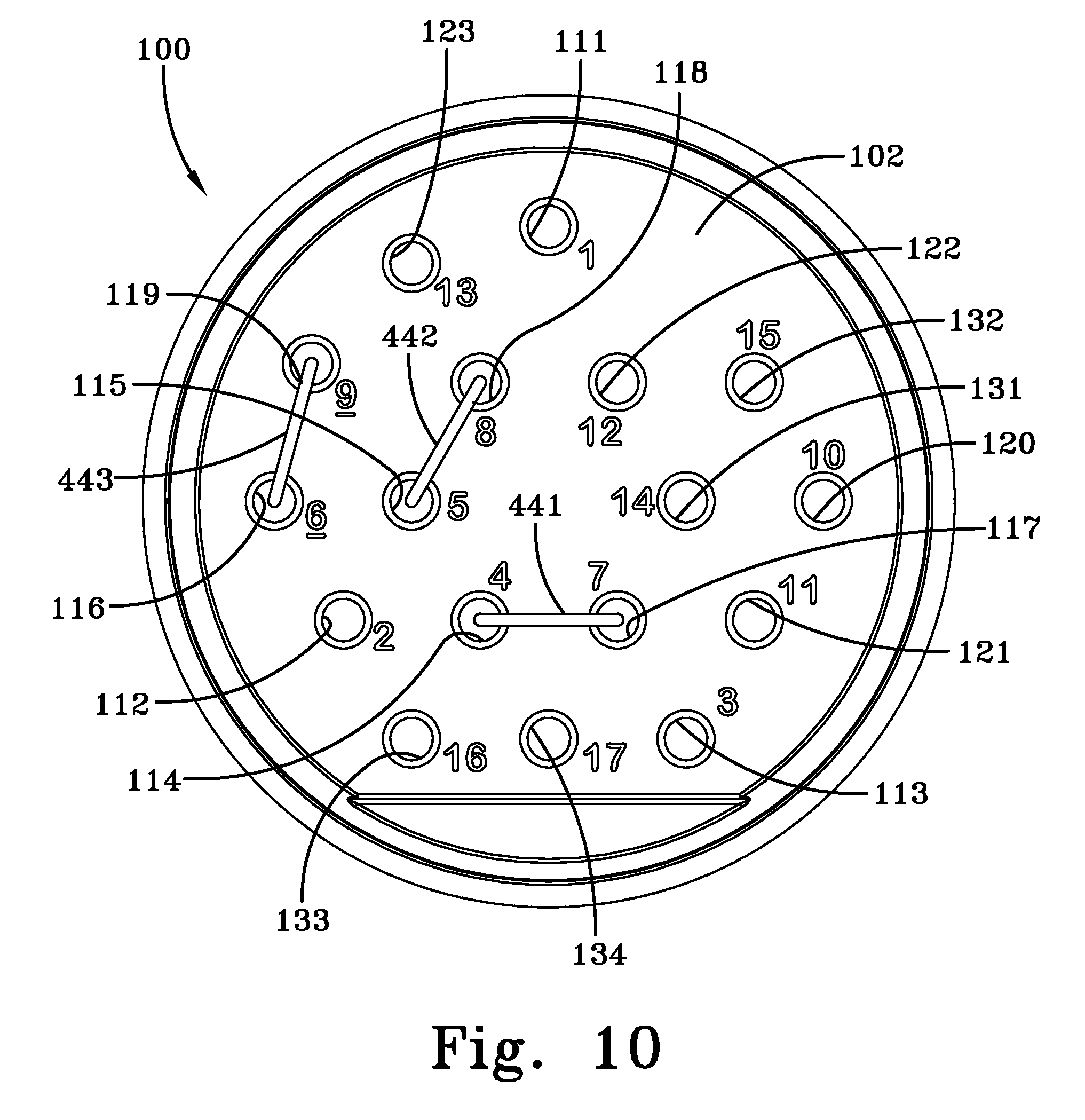
12 wire motor wiring diagram without start. Now you know how a starter motor works. A beginner’s guide to circuit diagrams. I am looking for anyone that can help me wire a 3 phase, 12 wire motor that someone has messed up the wire numbers.
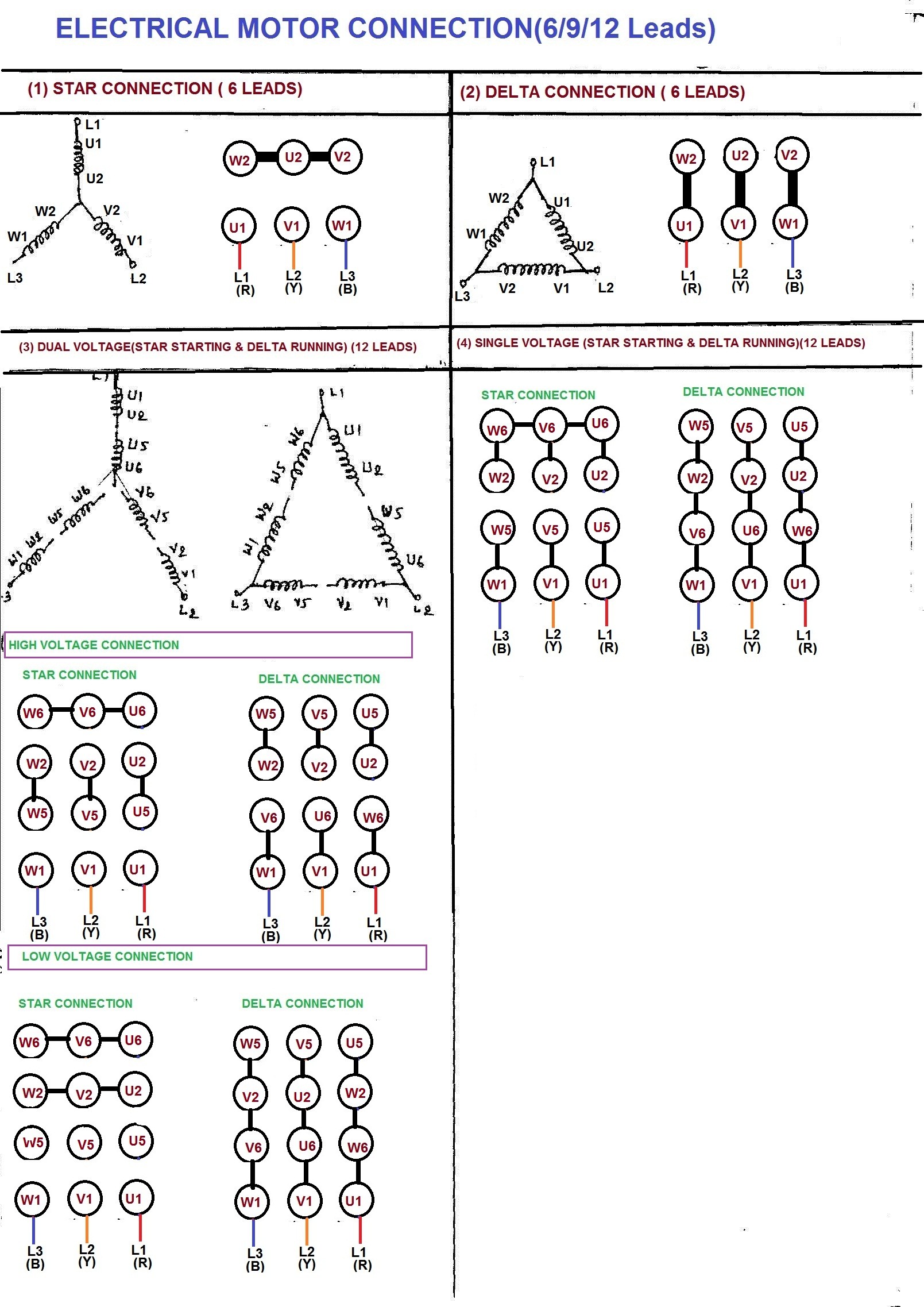
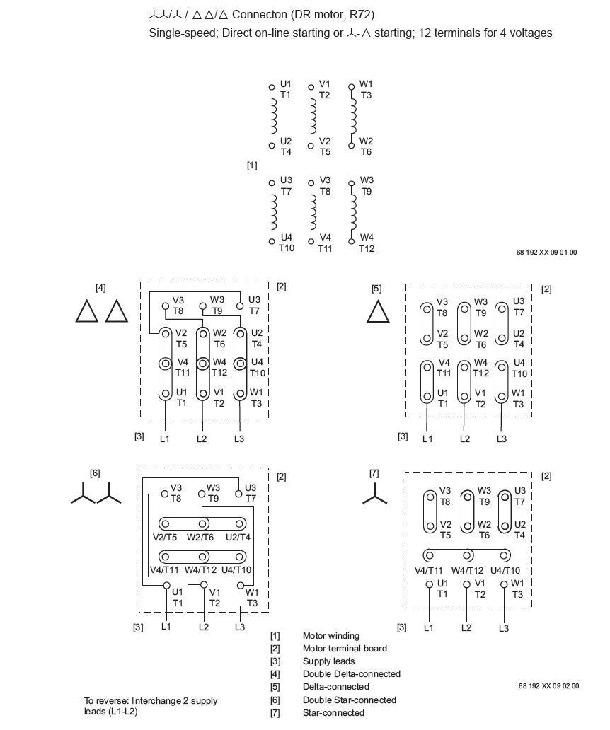
So the general wiring diagram on the nameplate will not work. Both windings must be identical as to size of wire and number of turns. Electrical motors 12 lead, dual voltage, wye start/delta run, both voltages or 6 lead, single voltage, wye start/delta run motors designed by us motors for wye start, delta run may also be used for across the.
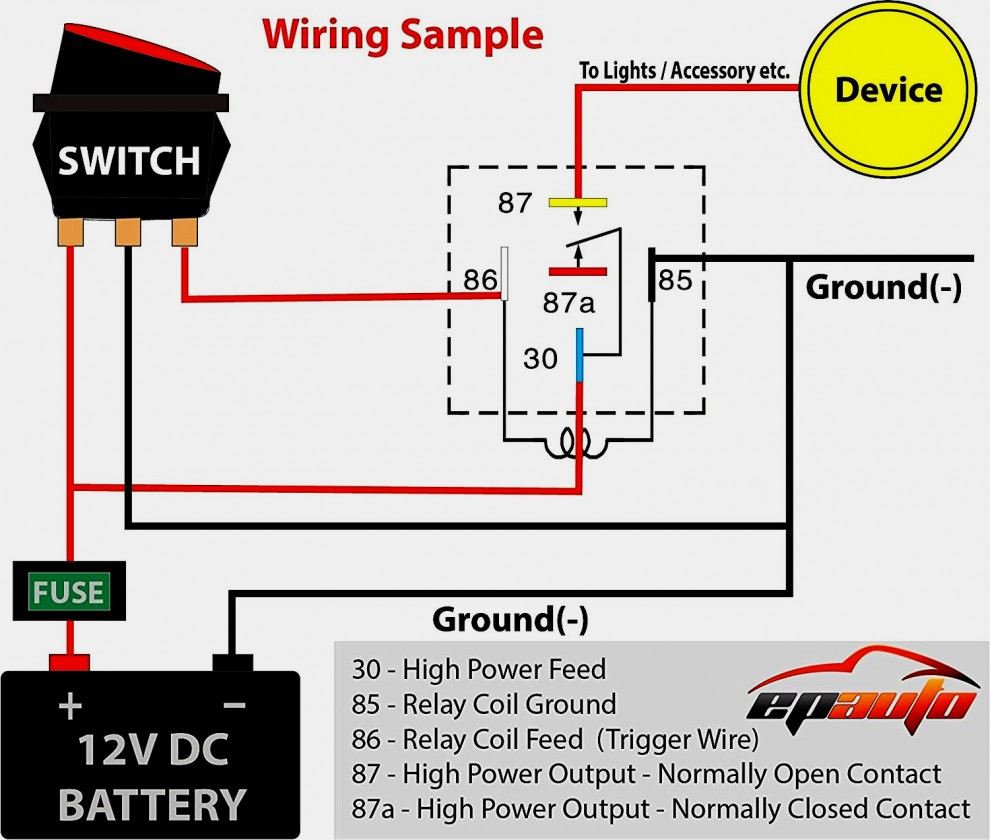
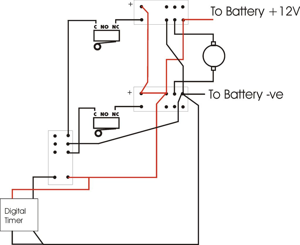
But what about the rest of the starting system? Starting circuit operation is fairly straightforward. Not every car carry the starter relay in starting system and the starter solenoid wiring diagram can be learned by with or without starter relay type.
Bosch starter motor wiring diagram. These diagrams are current at the time of publication, check the wiring diagram supplied with the motor. Printable graph paper electrical diagram ford tractors engine repair starter.
Reactor start split phase induction electric motor. 12 motor leads, no diagram. Each component ought to be placed and linked to different parts in.
If not, the structure will not work as it ought to be. 3 phase motor starter wiring diagram pdf source. The second part involves the control circuits.
I thought that i would start a new post for this, although it is in reference to the 25hp phase converter mentioned in one of my recent posts. A first look at a circuit diagram could be confusing, but if search for a subway map, look for schematics. L1 and l2 are designated as the two connection points representing the two.
2007 ford taurus fuse diagram 2007 ford taurus fuse diagram. Refer to the motor manufacturer’s data on the motor for wiring diagrams on standard frame ex e, ex d etc. Reactor start split phase induction electric motor.
It consists of instructions and diagrams for different kinds of wiring techniques as well as other products like lights, windows, and so on. This rpc that i purchased, came with absolutely no identifying marks on the motor. 800 x 600 px, source:
I only presume that it is 25hp because that is what i was told by the man who sold it to me. Inst maint & wiring.qxd 5/03/2008 10:02 am page 6 Each component should be set and connected with different parts in specific manner.
Wiring diagram consists of numerous detailed illustrations that display the relationship of assorted products. Single phase motor wiring diagram with capacitor start capacitor run. We did our best to keep this as simple and as easy to understand as possible.
They can be used as a guide when wiring the controller. When the driver turns the key to the “start” position in a typical starting system, battery voltage flows from the ignition. Phase 2 l1 l2 l3.
Low voltage parralel connection is lines 1&6&7&12,2&4&8&10,3&5&9&11. Electric starter motor assembly an electric starter will take stored electrical energy. 11 and 12 1.4 ohms.
Typical wiring diagrams always use wiring diagram supplied on motor nameplate connection diagrams (#co leads part winding) weg three phase motors volts / 12 lead / part winding 12 10 11 12 3 l1 l2 12 10. A wiring diagram is a streamlined conventional photographic representation of an electrical circuit. Collection of 4 pole starter solenoid wiring diagram.
Capacitor start capacitor run induction motors are single phase induction motors that have a capacitor in the start winding and in the run winding as shown in figure 12 and 13 wiring diagram. Feb 27, a lead wye start/delta run motor has the ability to meet several starting wye delta starter or by a series of contactors in a control circuit.motor wiring diagram 12 lead, dual voltage, wte start / delta run, both voltages € € € € € € us electrical motors per nema mg1 , a wye start, delta run motor is one arranged for starting by connecting to the supply. This is the standard nema connection for 12 lead delta for normal across the line starting.
Here is a basic wiring diagram that applies to all vintage and antique lawn and garden tractors using a stator charging system and a battery ignition system. 12 wire motor termination hi voltage series connection for 12 lead delta is 4&7 tied,5&8 tied,6&9 tied. Ac manual starters and manual motor starting switches 12 class 2510 12 class 2511 and 2512 13 2 speed ac manual starters and.
Atv starter solenoid wiring diagram you will need an extensive expert and easy to know wiring diagram. In split phase motors, changing the winding causes the motor to work in reverse. Draw out the basic high voltage delta circut and then go around the triangle, and label the windings as we go.
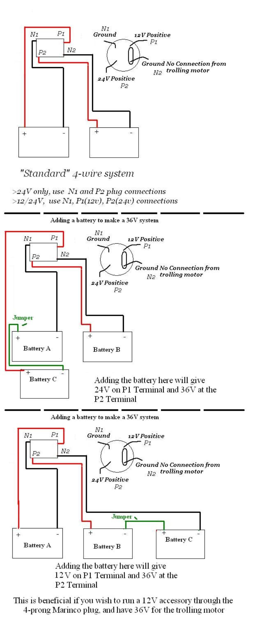
12 24 Volt Trolling Motor Wiring Diagram Collection Wiring Diagram Sample
Find Out Here Weg 12 Lead Motor Wiring Diagram Sample

Weg 12 Lead Motor Wiring Diagram Collection

3 Phase Motor Wiring Diagram 12 Leads Cadician's Blog
Baldor 12 Lead Motor Wiring Diagram Wiring Diagram

480 Volt 12 Lead Motor Wiring Diagram Https Www Hollandindustrial Com Wp Content Uploads Sites
Weg 12 Lead Motor Wiring Diagram
12 Lead Motor Wiring Diagram Discover The World Of Wedding Ideas
12 Volt Relay Wiring Diagram Wiring Diagram
12 Volt Winch Motor Wiring Diagram Collection Wiring Collection

12+ 12 Lead Motor Wiring Diagram Robhosking Diagram

12 24 Volt Trolling Motor Wiring Diagram Collection Wiring Diagram Sample
12 Lead 480 Volt Motor Wiring 9 Lead Single Phase Motor Wiring Diagram
12 Lead Motor Wiring Diagram Wiring Diagram
12+ Baldor Electric Motor Capacitor Wiring Diagram Wiring Diagram in 2020 Ac

12 24 Volt Trolling Motor Wiring Diagram Free Wiring Diagram

12 24 Volt Trolling Motor Wiring Diagram Free Wiring Diagram

480 Volt 12 Lead Motor Wiring Diagram Diagram Database Free Read Or Download Diagram Database
12/24 Volt Trolling Motor Wiring Diagram
